| modeling
material properties
meshing
loadings
solving
post-processing
Modeling:
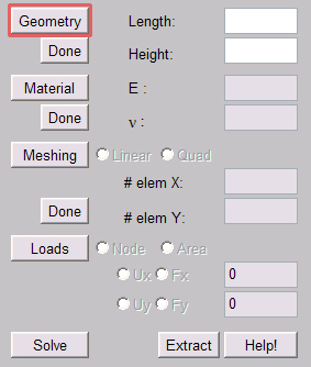
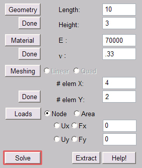
To begin the problem click the 'Geometry' button
to enable the textboxes. As in many finite element packages,
you do not specify units, only numbers for all physical
quantities. The program will interpret the quantities
in terms of a consistent set of units. For example,
length and height are interpreted as, say, meters or inches.
Enter the size of the beam in the textboxes.
This program is limited to rectangular shapes. The thickness
into the screen is assumed to be one.
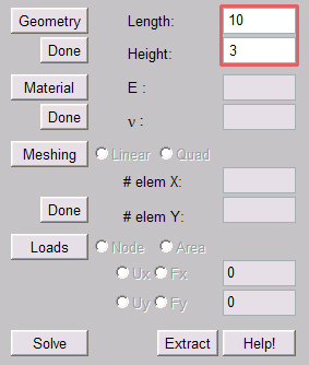
Click 'Done' when you have entered the
length and height of the beam
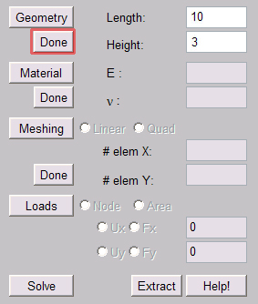
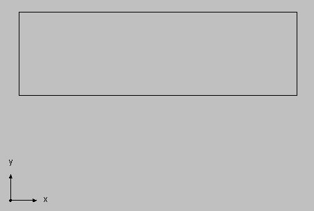
The modeling is now done. The output screen
should look like this:
top
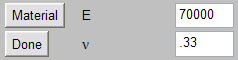
Material Properties:
The material properties you can define are
Elastic Modulus (E) and Poisson ratio (v).
To enter material properties, click the 'Material' button
to enable the textboxes. Enter the values of E and v.
Click 'Done' to set these values.
Although no units are specified, the Elastic
Modulus will be interpreted as having units consistent with
other quantities, say, Newtons/square meter or pounds/square
inch. Poisson ratio is unit-less.
Setting material properties does not change
the output screen
top
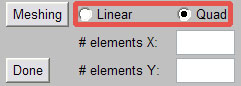
Meshing:
To create a mesh, click the 'Meshing' button
to enable the textboxes and buttons.
Select either the linear (4-node) element (actually
a pair of triangular elements) or the quad (9-node) element
using the circular buttons.
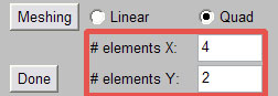
Enter the mesh size in the textboxes. Click
'Done' when you have entered the required data
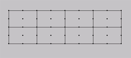
the output screen will now look like this.
(the dots represent nodes of the quad element - notice each
element has 9 nodes):
top
Loadings:
To apply loadings click the 'Loads' button
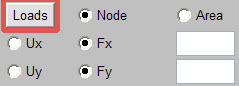
Single Point Force/Displacement
Select the 'Node' button to assign
a force or displacement to a single node. Then select the
Fx and Fy buttons to assign a force to the
node. Enter the force components into the respective textboxes.
The force is interpreted in terms of, say, Newtons or pounds.
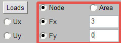
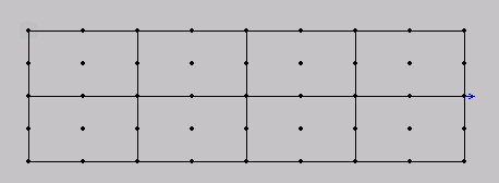
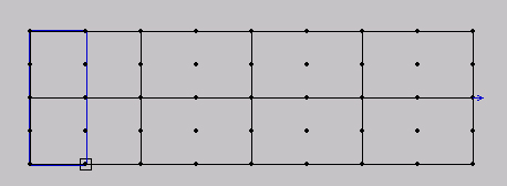
To assign this force to a node, use your mouse
to select (single-click) a node on the output screen. A
small blue arrow will appear after you click a node, indicating
the force has been set.
The same procedure can be repeated for other
nodes. You can assign displacements instead of forces.
Displacements are interpreted as say, meters or inches.
You can also combine forces and displacements. For example,
you could assign an X displacement of 0.3 and a Y force
of 5 to a single node.
Multiple Forces/Displacements
To assign a force to multiple nodes, select
the 'Area' button. Then select the Ux and
Uy buttons to assign the displacement to multiple
nodes. Enter the displacement components into the
respective textboxes. In this example we will assign zero
X and Y displacement to all the nodes on the left edge of
the beam.

The displacements will be assigned to all
the nodes in the area between two selected nodes. To select
this area, click the first node once, then click the second
load once. The displacements will be assigned to all nodes
between these two points.
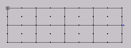
Select first node. A blue rectangle will appear
to guide your selection:
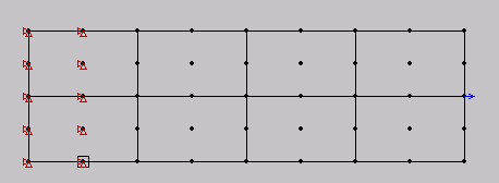
Select second node. The blue rectangle will
show you the enclosed nodes before you make a selection:
The result is:
The same procedure can be repeated for other
areas. You can assign forces instead of displacements. You
can also combine forces and displacements. For example,
you could assign an X displacement of 0.3 and a Y force
of 5 to any area of nodes.
top
Solving:
Once geometry, material properties, meshing,
and loadings are set, the problem can be solved. To solve
the problem simply click the 'Solve' button.
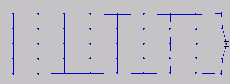
The output screen will now display the solution
in the form of a deformed mesh.
top
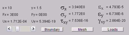
Post Processing:
After pressing 'Solve' data from any
node is available simply by moving the mouse over the node.
For example, move your mouse over the right-most node and
you will see the following data in the post-processing menu.
Displacements are interpreted as, say meters or inches, stresses
as Newtons/square meter or pounds/square inch, and strains
are unitless. By clicking on the buttons 'Boundary'
and 'Mesh' you can turn off and on whether the original
boundary and mesh are shown. By clicking on the button
'Loads' you can turn off and on whether the loads are
shown. Likewise, when you move the slider all the way to the
left (undeformed) the loads appear.
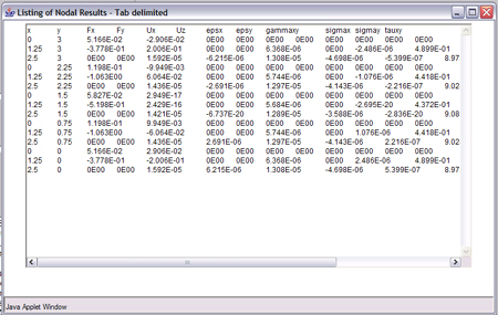
To extract nodal results in a tab-delimeted
format for external processing in a spreadsheet program, such
as Microsoft Excel, click the 'extract' button next
to 'Help!' You will then follow the same procedure
for applying loads on an area or line. Click the first node,
then click the second node. A blue rectangle will guide your
selection. After clicking the second node, a pop-up window
will appear with the selected nodal results:
top
|